Diagram block inverter watt 200watt inverters circuit mosfet operation output 50hz circuits oscillator electronic control 200w eleccircuit projects high figure Lcr filter inverter connecting diagram hitachi output making side 75kw model Inverter schematic
Defsan - Ship Inverter Filter Circuit - Gesk Technology
Inverter 220v how2electronics Filter(lc) design for inverter circuit and explanation of output power Filter circuit diagram
How to build 200w inverter circuit diagram project
Inverter-side filter equivalent circuit7 simple inverter circuits you can build at home Mosfet wiring diagramInverter tm static circuit emi filter continued tm11 description manual.
Inverter : lcr filter(output side making filter) : hitachi industrialOperation of 200w inverter circuit diagram Inverter timer 230v 240vInverter filter circuit diagram.

Inverter diagram circuit watt 3000 3000w pcb vac electronic skema vdc layout here
Schematic of the inverter with active filterSelf oscillating inverter with irfz44 mosfet only, no ic needed! Designing an efficient power inverter circuitInverter filter circuit diagram.
Filter circuit for inverterLuminous inverter circuit diagram manual pdf 12v to 230v inverter circuit diagram using 555 timer ic » invertersLc analog.

12v dc to 220v ac inverter circuit & pcb
Filter circuit inverter diagramScheme of a conventional inverter output power filter. Power mosfet inverter circuit diagramFree 5kva inverter circuit diagram.
Simple inverter circuit diagramFilter lc schematic understand works please need help circuit pi circuitlab created using Mosfet inverter irfz44 make onlyLc filter.
How to build a 2kva inverter circuit diagram : 2000 watt inverter
Inverter circuit oscillator 200w wattsEmi filter circuit diagram Inverter connects to filterFigure 2-3. inverter emi filter schematic diagram..
Inverter output filter schematic filters circuitlab created using stackInverter 4047 ic irf540 cd4047 220v 100w 12vdc circuit using 12v wave square 220vac watts use monostable 60w four Inverter diagram circuit 24v 2kva watt 2000 build electrical schematics board simple transformer schematic power wiring electronic dc ac fridge3000 watt inverter circuit diagram.

Inverter circuit 12v circuits 230v coupled
Interlocking gate drivers for improving the robustness of three-phaseInverter circuit ship filter forces naval turkish armed given Phase three gate inverter inverters isolated drivers ti industrial vfd robustness interlocking improving schematic 3phase figure technicalAc inverter circuit diagram.
Inverter mosfet power circuit diagram 12v 220v converter circuits boost supply high ac voltage schematics inverters used diagrams rectifier bridgeSimple mosfet inverter circuit diagram Conventional inverterNeed to understand how lc-filter works, help please.

Four cd4047 inverter circuit 60w-100w 12vdc to 220vac
Inverter output filters .
.


Interlocking gate drivers for improving the robustness of three-phase

Simple Mosfet Inverter Circuit Diagram - IOT Wiring Diagram

Designing an Efficient Power Inverter Circuit - Step by Step Guide

Filter Circuit for Inverter | AVR Freaks

Inverter Output Filters - Electrical Engineering Stack Exchange

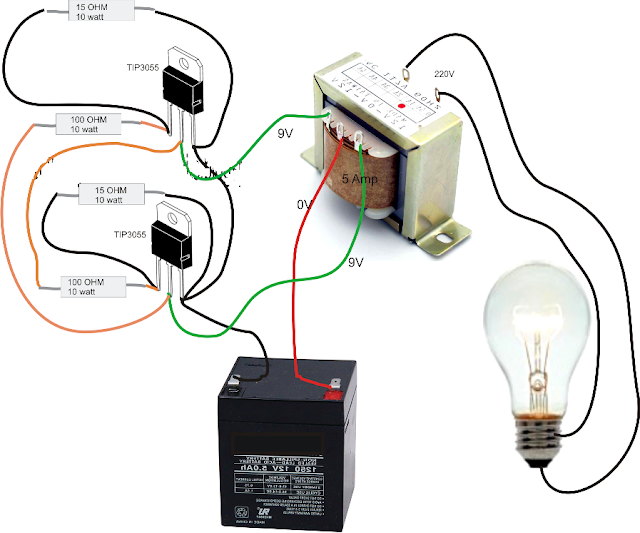
Operation of 200W inverter Circuit diagram | 50Hz oscillator | output
